Temank PWM Inverter & Charger PC/ MPC PS-3K With 2-3KVA LCD Display Success Active

Notice:
PV Connection (Only apply for the model with solar charger)
CAUTION: Before connecting to PV modules, please install separately a DC circuit breaker between inverter and PV modules.
WARNING! All wiring must be performed by a qualified personnel.
WARNING! It's very important for system safety and efficient operation to use appropriate cable for PV module connection. To reduce risk of injury, please use the proper recommended cable size as below.
|
Typical Amperage |
Gauge |
Torque Value |
|
50A |
8 AWG |
1.4-1.6 Nm |
PV Module Selection: (Only for the model with PWM solar charger)
When selecting proper PV modules, please be sure to consider below requirements first:
- Open circuit Voltage (Voc) of PV modules not exceeds max. PV array open circuit voltage of inverter.
INVERTER MODEL HPS12V1500VA HPS24V1500VA HPS24V3000VA Rated Out Power 12V 24V Charging Current (PWM) 50Amax. Max. PV Array Open Circuit Voltage 55Vdc 80Vdc - Max. Power Voltage (Vmpp) of PV modules should be close to best Vmp of inverter or within Vmp range to get best performance. If one PV module can not meet this requirement, itS necessary to have several PV modules in series connection. Refer to below table.
Model Best Vmp Vmp range HPS12V1500VA 15Vdc 15V~20V HPS24V1500VA 30Vdc 30V~40V HPS24V3000VA
Note: * Vmp: panel max power point voltage.
The PV charging efficiency is maximized while PV system voltage is close to Best Vmp.
Maximum PV module numbers in Series: Vmpp of PV module *Xpcs = Best Vmp of Inverter or Vmp range
PV module numbers in Parallel: Max. charging current of inverter / Impp
Total PV module numbers = maximum PV module numbers in series * PV module numbers in parallel
lake HPS12V1500VA inverter as an example to select proper PV modules. After considering Voc of PV module not exceeds 55Vdc and max. Vmpp of PV module close to 15Vdc or within 15Vdc ~ 20Vdcz we can choose PV module with below specification.
- Brand: Temank
- Product Model: HPS-3K-24V
- Technology:PWM
- LCD Screen Display
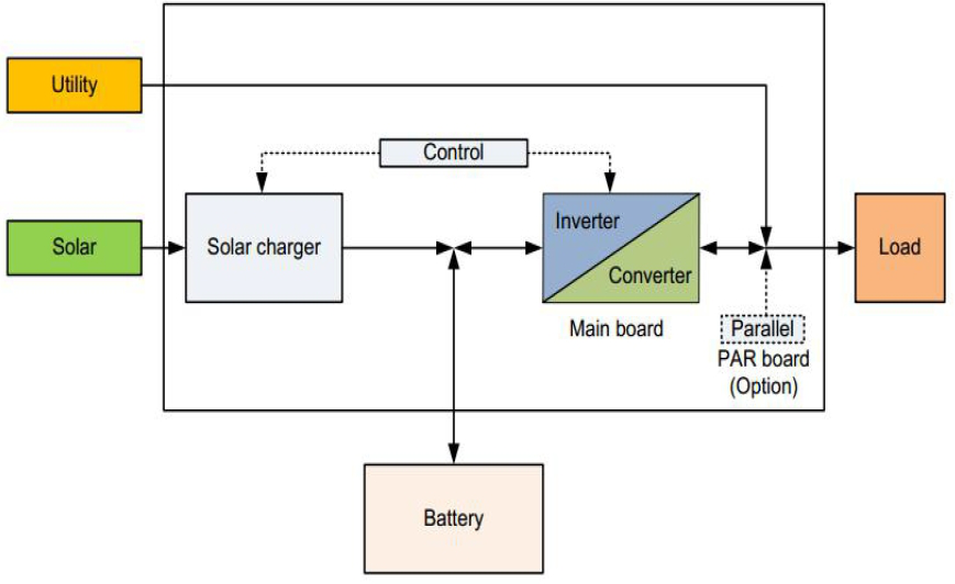
Temank PWM Inverter Charger Basic Topology Introduction
The topology for 2KVA/3KVA shows as below:

Fault and Troubleshooting
|
No LCD |
|
First to test battery volt to check whether it is in range of 22V-26V; |
|
Fault 01 |
Fan is locked when inverter is off. |
First to replace the fan, to check whether it is ok; if NO, please |
|
Fault 02 |
Over temperature |
Please to check the main board and repair according to 3.8 |
|
Fault 03 |
Battery voltage is too high |
Please to check first and then to repair the main board according |
|
Fault 04 |
Battery voltage is too low |
Please check the battery’s voltage. If voltage is too low, please charge it. |
|
Fault 05 |
Output short circuit or over temperature is detected by internal converter components. |
First to start up the inverter by only connecting battery, if the fault is still on, please inspect the main board following 3.3 and 3.4. |
|
Fault 06 |
Output voltage is abnormal. (For 1K/2K/3K) |
First to start up the inverter by only connecting battery, if the fault is still on, please inspect the main board following 3.3. |
|
Fault 07 |
Overload time out |
Please turn off the loads, and restart the inverter again. |
|
Fault 08 |
Bus voltage is too high |
Please check the BUS circuit of the main board according to 3.5. |
|
Fault 09 |
Bus soft start failed |
To check the main board following 3.1.2, 3.2.1, 4.1 and 4.2 and to repair accordingly |
|
Fault 11 |
Main relay failed |
Please check the relay whether work. |
To Check AC Charging Circuit
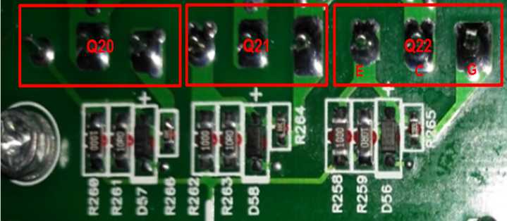
To Check Power Components
Q20,Q21,Q22: MOSFET SLW/SVF3878PN 9A 900V

|
Positioning |
Attribute |
Reference Value |
Failure Status |
|
Q20,Q21,Q22 |
Diode |
EC: 0.38V |
Short Circuit |
Note: If there is one or more than one components broken, please replace them all.
Drivers
R259,R261,R263: SMD Resistor CHIP TF 1/4W 10 F(1206)
R258,R260,R262: SMD Resistor CHIP TF 1/4W 100 F (1206)
D56/D57/D58: SMD Diode ROHS D PANJIT/IN4148W 0.15A 75V SMD

|
Positioning |
Attribute |
Reference Value |
Failure Status |
|
R259,R261,R263 |
Resistor |
10 ohm |
Open Circuit |
|
R258,R260,R262 |
Resistor |
100 ohm |
|
|
D56/D57/D58 |
Diode |
EC: 0.6V |
Short Circuit |
|
Note: When test diodes, please remove R259, R261, R263, otherwise the test result is not right. |
|||
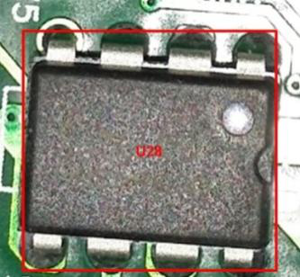
UC3843: U28

|
Positioning |
Attribute |
Reference Value |
Failure Status |
|
U28(UC3843) |
Resistor |
Pin7-Pin5: 42K ; Pin6-Pin5: 30K |
Short Circuit |
To Check Rectifier Circuit
Charging Circuit
D21/D22/D23: Plug-in Diode ON/MBR30200C 30A 200V SCKY RAD BULK

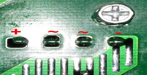
REC1: D.GI/GBUM8M 8A 1000V BRIDGE

|
Positioning |
Attribute |
Reference Value |
Failure Status |
|
D21/D22/D23 |
Diode |
P to N: 0.44V ; N to P: OL |
Short Circuit |
|
REC1 |
Diode |
~ to +: 0.50V ; + to ~: OL |
There is detail information about Temank PWM Inverter & Charger PC/ MPC PS-3K-110V LCD Display as below:
Temank PWM Inverter & Charger PC/ MPC PS-3K With 2-3KVA LCD Display Manual
Powmr 50Amp 24VDC 3KVA Hybrid Inverter Solar Charge Controller


