- Product Brand: Temank
- Model No.: Tracer6415AN
- Certification: CE certification(LVD EN/IEC62109,EMC EN61000-6-1/3)
- High quality & low failure rate components of ST and Infineon to ensure the product’s life
- Advanced MPPT technology & ultra-fast tracking speed, with tracking efficiency no less than 99.5%
- Maximum DC/DC transfer efficiency is as high as 98.6%★ , full load efficiency is up to 98%★
- Advanced MPPT control algorithm will minimize the MPP loss rate and loss time
- The accuracy of the recognition and tracking at the highest point of multiple-peaks MPP
- The wider range of MPP operating voltage.
- Auto control system to limit the charging power & current go over the rated value.
- Support 4 charging options: Sealed, Gel, Flooded and User.
- Support the lead-acid
- Real-time energy recording and statistical function
- Automatic over-temperature power reduction function
- Hundred percent full load operation in working environment temperature range within charging & discharging
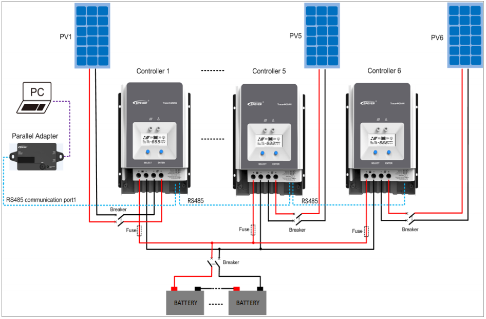
- Support up to 6 units in parallel to expand system
- Load relay control external load switch signal to realize diversified load work modes
- The first and the second disconnection of load control, contain two relay’s contact.
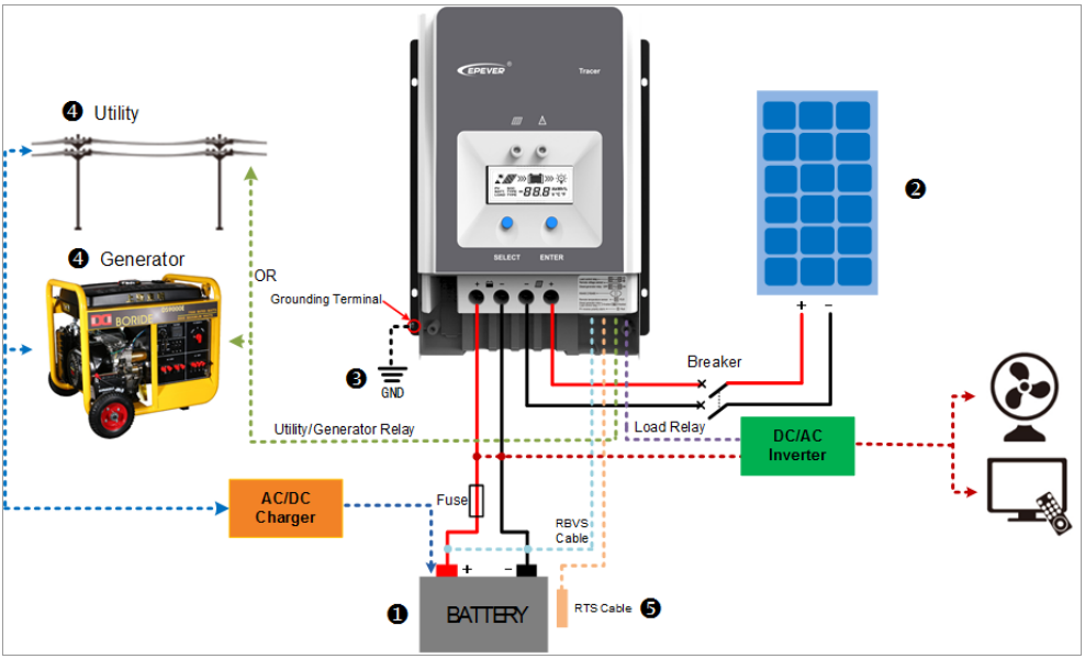
- Auto-control of utility and generator relay design
- Utility or generator auto-control relays make it easy to compose the hybrid power system
- The remote temperature and the voltage sensor design will collect accurate data of battery temperature and voltage
- Isolated RS485 with 5VDC/200mA to protect output for no power devices with MODBUS protocol
- To monitor or set the parameters by using the phone Apps or PC software.
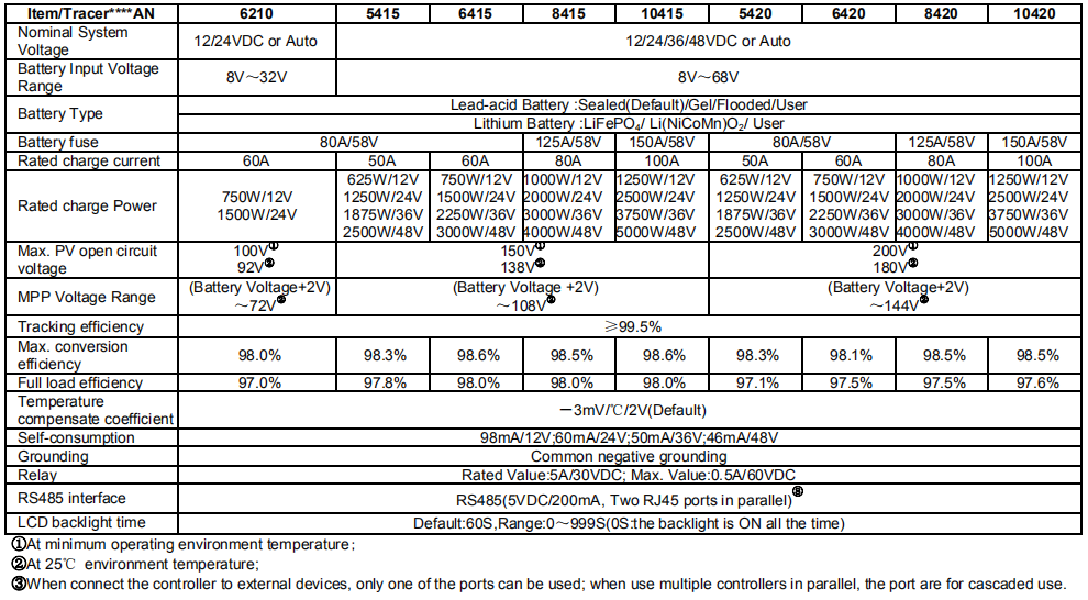
Solar Charge Controller Tracer Series Products Specifications:
Relay instruction
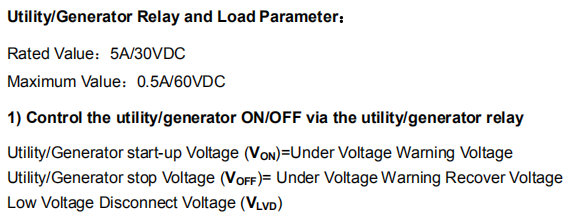
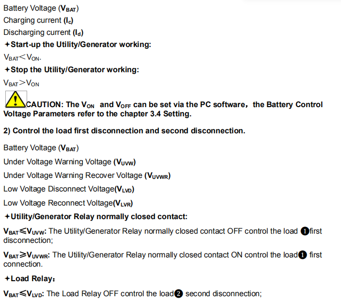

Refer to the below the diagram:
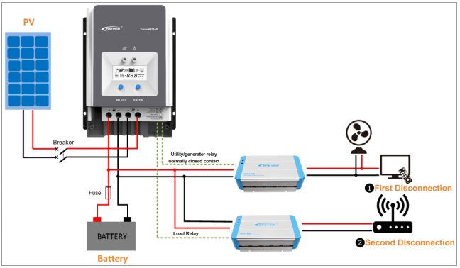
One Solar Charge Controller:
Multiple Solar Charge Controller:

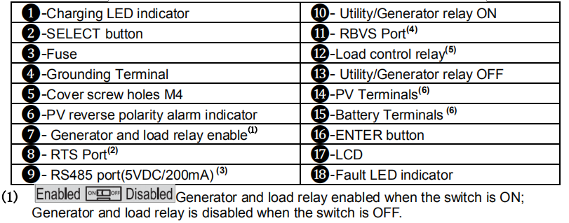

Designations of Controller Models

Accessories (Included)


Installation
General Installation Notes
- Before installation, please read through the entire installation instructions to get familiar with the installation steps.
- Be very careful when installing the batteries, especially flooded lead-acid battery. Please wear eye protection, and have fresh water available to wash and clean if any contact with battery acid.
- Keep the battery away from any metal objects, which may cause short circuit of the battery.
- Explosive battery gases may come out from the battery during charging, so make sure ventilation condition is good.
- The controller can work with lead-acid battery and lithium battery within its control scope.
- Ventilation is highly recommended if mounted in an enclosure. Never install the controller in a sealed enclosure with flooded batteries! Battery fumes from vented batteries will corrode and destroy the controller circuits.
- Loose power connections and corroded wires may result in high heat that can melt wire insulation, burning surrounding materials, or even causing fire. Ensure tight connections and use cable clamps to secure cables and prevent them from swaying in mobile applications.
- Battery connection may be wired to one battery or a bank of batteries. The following instructions refer to a singular battery, but it is implied that the battery connection can be made to either one battery or a group of batteries in a battery bank.
- Multiple same models of controllers can be installed in parallel on the same battery bank to achieve higher charging current. Each controller must have its own solar module(s).
- Select the system cables according to 5A/mm2 or less current density in accordance with Article 690 of the National Electrical Code, NFPA 70.
PV Array Requirements
(1)Serial connection (string) of PV modules

(2) PV array maximum power
The MPPT controller has the function of current/power-limiting, that is, during the charging process, when the charging current or power exceeds the rated charging current or power, the controller will automatically limit the charging current or power to the rated charging current or power, which can effectively protect the charging parts of controller, and prevent damages to the controller due to the connection of some over-specification PV modules. The actual operation of PV array is as follows:

Wire Size
The wiring and installation methods must conform to all national and local electrical code requirements.
PV Wire Size
Since PV array output can vary due to the PV module size, connection method or sunlight angle, the minimum wire size can be calculated by the Isc* of PV array. Please refer to the value of Isc in the PV module specification. When PV modules connect in series, the Isc is equal to a PV modules Isc. When PV modules connect in parallel, the Isc is equal to the sum of the PV module’s Isc. The Isc of the PV array must not exceed the controller’s maximum PV input current. Please refer to the table as below:
NOTE: All PV modules in a given array are assumed to be identical.
*Isc=short circuit current(amps) Voc=open circuit voltage.
Please view the document about EPever 100A MPPT Solar Charge Controller as below:
EPever 100A MPPT Solar Charge Controller Manual Tracer6415AN


